
PhaSe 1
Áudio válvulas 6C33
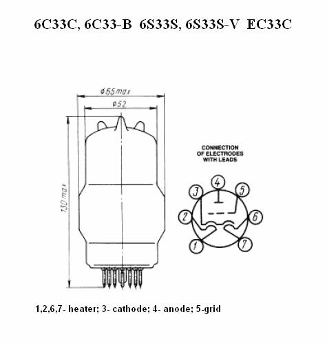

Válvula 6C33C, note a construção
robusta e as colunas internas que suportam os eletrodos e vão em toda a extensão
da válvula desde a base ao topo. Esta válvula marcou uma nova era na aplicação
de válvulas em circuitos eletrônicos.
![[Mig25d.jpg]](audioampdecar_arquivos/image008.jpg)
Tudo começou com o Mikoyan-Gurevich MiG-25 o supersônico de até Mach 3.2 (o "Foxbat" para a NATO) cujo primeiro protótipo voou em 1964.
Em 6 de setembro de 1976 quando Viktor Belenko desertou de uma base aérea soviética na Sibéria oriental, para o aeroporto da Hakodate na ilha de Hokkaido no Japão por ser esta a mais próxima da Sibéria, uma vez que seus tanques eram mantidos quase vazios, apenas para testes permanentes para o caso de emergências. Este seu vôo e aterrisagem no Japão teve que ser feito às pressas e quase causa um acidente num avião de carreira que levantava vôo neste exato momento.
Devidamanete “convencido”, Belenko desapareceu, surgindo com outra identidade e fisionomia, sem se saber quem ao certo, e talvez imediatamente transferido aos Estados Unidos. O avião foi devidamente desmontado sem qualquer espera e enviado para análise ao the Foreign Technology Division (agora the National Air and Space Intelligence Center) da the United States Air Force, na Air Force Base the Wright-Patterson perto de Dayton, Ohio. Depois de exatos 67 dias, foi devolvido em pedaços para o governo russo.
Nesta operação veio-se a descobrir que entre outras características incríveis do MiG-25, o seu radar (uma verdadeira obra prima...) que funcionava a…válvulas, tinha o alcance de 50 Km mas a forma como se concebia que esse radar de potência bruta: 600 kW!... Suficientes para cozinhar um coelho a 1000m de sua emissão e danificar os equipamentos de ECM (detetores eletrônicos de presença) do avião inimigo.
Esta válvula, específicamente a 6C33 era utilizada na regulação de tensão da fonte.
O sistema operacional à válvulas também tornava o equipamento imune a danos causados por pulsos eletromagnéticos gerados em explosões nucleares, tinha mais fácil manutenção e era mais tolerante à variações térmicas dispensando equipamentos complexos de sazonamento, que são exigidos quando se usam componentes de estado sólido.
Entre outros problemas que ocorrem num projeto de avião como este, é a metalurgia construtiva que os soviéticos resolveram com o uso de materiais convencionais usando predominantemente o aço-níquel e não o caríssimo titânio, e que por causa do peso do aço exigia motores mais potentes e mais gastadores de combustível.
O avião possuía concepções únicas tais como o corpo e as asas divididas em compartimentos estanques que serviam de depósito de combustível.
Em 31 de agosto de 1977 o MiG-25 modelo E266M pilotado por Alexander Fedotov atingiu o record absoluto de altitude pelas próprias turbinas de 123,523.58 ft (37,650 m) em Podmoskovnoye, URSS.
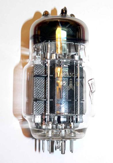
Outra vista da 6C33 com melhor visão dos componentes internos.
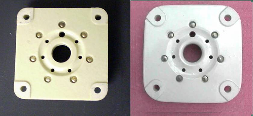
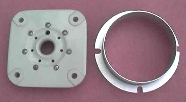
Septar type base
À esquerda de fabrico americano à direita de produção russa. Abaixo com anel de centragem removível.
Septar socket for tubes such as 4-65, 6C33, 829B, 6S33S / 6C33C, GI-30 and GU-32, etc. Russian copy of EF Johnson part.
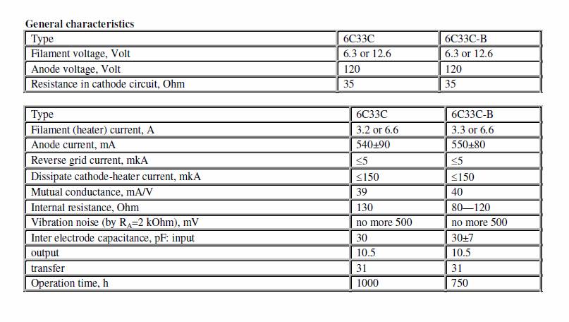
Data
of 6C33C
Max data
|
Max anode voltage |
400 |
|
Anode dissipation |
60 W |
|
continuous cathode current |
600 mA |
|
Overall length |
133 mm max |
|
Diameter |
max 64 mm |
Typical data
|
Anode voltage |
120 |
|
Anode current |
550 mA |
|
Transconductance, gm |
40 mA/V |
|
Anode resistance |
80 ohm |
|
Grid voltage |
-19 V |
|
Heater voltage |
6.3 V |
|
Heater current |
6.4 A |
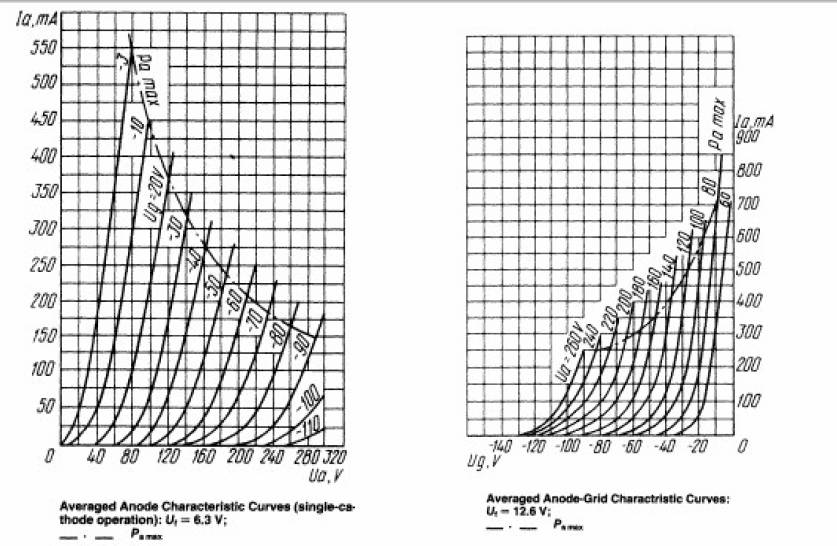
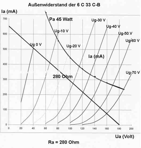
Resistência de carga para 6C33
Na fonte de alimentação da unidade de rádio principal do MiG-25 era utilizada uma válvula triodo até então desconhecida. Sua designação militar era 6C33C e era usada como reguladora de tensão. As características técnicas desta válvula eram muito superiores do que qualquer outra já produzida no ocidente.
A firma SanEi do Japão importou algumas válvulas 6C33C para a aplicação audio em 1997, rebatizando-as EC33C para o consumidor japonês.
O Sr. Dakesue no Japão foi a primeira pessoa a projetar um amplificador de potência com 6C33C-B em OTL em 1977.
As características principais do 6C33C são: transcondutância muito elevada, capacidade de corrente elevada e baixa resistência interna. Como estas válvulas são direcionadas para uso em aviões miltares suas construções mecânicas são muito robustas. O equivalente ocidental mais próximo é a 6336 mas os dados de 6C33C são bem superiores.
|
Tube |
6336A |
6C33C |
|
Gm |
27 mA/V |
40 mA/V |
|
Rp |
100 ohm |
80 ohm |
|
Max continuous anode current |
200 mA |
600 mA |
|
Heater current |
5A |
6.4A |
Data for the 6336A is
for both sections in parallel
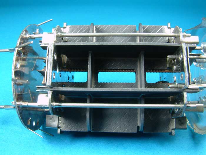
Conheça internamente a 6
C 33 C
As fotografias a seguir são cooperação de
Siegfried Neumann que por causa de
um desatre por ter rolado de sua mesa ao chão, resolveu demonstrar-nos o
conteúdo interno da válvula.
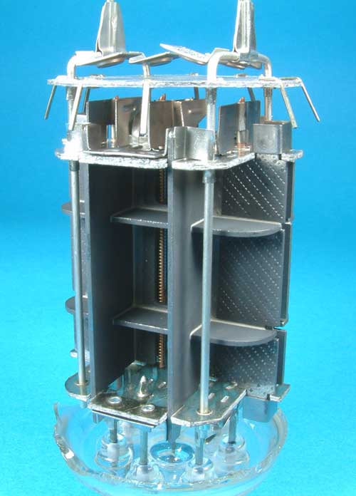
A fotografia abaixo mostra os quatro enormers getters posicionados
no topo nas colunas da “catedral”.
A fotografia adiante mostra os dois enormes catodos responsáveis pela elevada corrente manipulada.
Mathias “pica-pau” também quebrou acidentalmente uma 6C33 C e
demonsstrou que o anodo é feito de lâmina de aço através do teste com o imã.

As fotografias de Romy “the Cat” - www.goodsoundclub.com/Forums/ mostra uma seqüência evolutiva.
A partir da direita a 6C18C de 1963, a 6C18C de 1968 ea 6C33C de 1980.
Michael
Boele nos traz os dados completos da válvula 6C33.
xxxxxxxxxxxxxxxxxxxxxxxxxxxxxxxxxxxxxxxxxxxxxxxxxxxxxxxxxxxxxxxxxxxxxxxxxxxxxxxxxxxxxxxxxxxxxxxxxxxxxxxxxxxxxxxxxxxxxxxxxxxxxxxxxxxxxxxxxxxxxxxxxxxxxxxxxx
Typical operating data:
Filament Current
Serial heater connection – filament voltage 12,6 V 3,3 ± 0,3 A
Parallel heater connection – filament voltage 6,3 V 6,6 ± 0,6 A
Typical Operation
Plate voltage 120V
Cathode resistor for cathode bias 35 Ohms
Warm-up time to steady state ³ 600 s1
Plate current 550 ± 80 mA2
1 Warm-up time to 90% emission £ 120 s.
2 Older versions and 6C33C/6S33S 540 mA ± 90 mA.
xxxxxxxxxxxxxxxxxxxxxxxxxxxxxxxxxxxxxxxxxxxxxxxxxxxxxxxxxxxxxxxxxxxxxxxxxxxxxxxxxxxxxxxxxxxxxxxxxxxxxxxxxxxxxxxxxxxxxxxxxxxxxxxxxxxxxxxxxxxxxxxxxxxxxxxxxx
Transconductance
Filament voltage 6,3/12,6V~ 40 ± 10 mS (= mA/V)3
Filament voltage 5,7/11,3V~ ³ 24 mS (= mA/V)
Internal resistance Rp 80..1204
Amplification factor m/mu 2,7 (2,5..4)
Reverse grid current £ 5 uA (Ug = -0,5 V)
Leakage currents
between plate and all other electrodes £ 30 uA
between grid and all other electrodes £ 20 uA
between cathode and heater filaments £ 150 uA
(leakage measured at maximum envelope temperature)
Vibration-induced noise voltage
(plate load 2 kOhm , vibration 10g 10..300 Hz) £ 500 mV
Internal inter-electrode capacitances
Input (Ce) 30 ± 7 pF
Output (Ca) 10,5 ± 1 pF
Transfer (Cga) 31 ± 7 pF
Cathode to heater £ 60 pF5
Rated Service Life under above operating conditions ³ 750 h6,7
Criteria for End of Service Life:
Reverse grid current ³ 15 uA
Plate current £ 340 mA
Reduction of emission compared to new valve ³ 30 %
3Older versions and 6C33C/6S33S gm = 39 ± 11 mS.
4 Older versions and 6C33C/6S33S Ri £ 130 Ohm.
5 Older versions and 6C33C/6S33S Cfk £ 70 pF.
6 If envelope temperature and shock/vibration are kept low, the life expectation under the electrical conditions given above will exceed 2000 h.
7 Rated service life inside environmental condition ratings for 6C33C/6S33S 1000 h, for 6C33C-EB/6S33S-EV 3000 h.
xxxxxxxxxxxxxxxxxxxxxxxxxxxxxxxxxxxxxxxxxxxxxxxxxxxxxxxxxxxxxxxxxxxxxxxxxxxxxxxxxxxxxxxxxxxxxxxxxxxxxxxxxxxxxxxxxxxxxxxxxxxxxxxxxxxxxxxxxxxxxxxxxxxxxxxxxx
Absolute Maximum Ratings:
Exceeding these ratings will cause permanent damage and/or premature failure of the valve. The circuit
design has to assure that these absolute maximum ratings are not exceeded under any circumstances
(worst case component tolerances and aging, environmental conditions and mains voltage deviations).
Filament voltage
Serial connection of heater filaments 11,3 V .. 13,9 V
Parallel connection of heater filaments 5,7 V .. 6,9 V
Plate voltage
Dissipation > 30 W 250 V
Dissipation £ 30 W 450 V
Zero Current at power-up 600 V
Negative grid voltage –0,5 V .. -150 V
Grid circuit resistance 200 kOhm8
Voltage between cathode and heater ± 300 V
Envelope temperature (J)
Ambient J = 20° C 260° C
Ambient J = 100° C 300° C9
Ambient J = 150° C 320° C10
Plate current
One triode operating 350 mA
Both triodes operating 600 mA
Plate dissipation
One triode operating 45 W
Both triodes operating 60 W
8Valid for fixed negative grid voltage. In actively servo-controlled loop, in which the grid bypass resistor forms at the same time the plate load of the
servo amplifier valve, a maximum value of 1,5 MOhms is permissible.
9 Maximum duration 100 h.
10 Maximum duration 2 h.
xxxxxxxxxxxxxxxxxxxxxxxxxxxxxxxxxxxxxxxxxxxxxxxxxxxxxxxxxxxxxxxxxxxxxxxxxxxxxxxxxxxxxxxxxxxxxxxxxxxxxxxxxxxxxxxxxxxxxxxxxxxxxxxxxxxxxxxxxxxxxxxxxxxxxxxxxx
Environmental Conditions11:
In the table, environmental conditions are specified whic h shall be survived by any sample valve taken
from a production batch without suffering permanent degradation. They do not, however, represent
sensible operating conditions for maximum valve performance and service life.
Vibration (10-300 Hz) 6 g 12
Multiple impacts (duration £ 50ms) 150 g13
Single impact (duration £ 50ms) 500 g14
Constant acceleration 100 g15
Operating temperatures (ambient) -60° C .. +100° C16
Relative humidity (at ambient J17 = + 40° C) 98 %
11 Valid for 6C33C-B/6S33S-V (750h rated service life) and 6C33C-EB/6S33S-EV (3000 h rated service life).
12 Older versions and 6C33C/6S33S 4 g.
13 Older versions and 6C33C/6S33S 10 g.
14 Older versions and 6C33C/6S33S 35 g.
15 Older versions and 6C33C/6S33S 10 g
16 Older versions and 6C33C/6S33S - 60° C .. + 70° C
17 J = temperature.
xxxxxxxxxxxxxxxxxxxxxxxxxxxxxxxxxxxxxxxxxxxxxxxxxxxxxxxxxxxxxxxxxxxxxxxxxxxxxxxxxxxxxxxxxxxxxxxxxxxxxxxxxxxxxxxxxxxxxxxxxxxxxxxxxxxxxxxxxxxxxxxxxxxxxxxxxx
Maximum ratings for extended service life:
The ratings given under the heading ‘Absolute Maximum Rating’ are valid for a rated service
life of 750 h and average reliability.
If a longer service life or high operational reliability is required, maximum ratings for current,
power dissipation and envelope temperature must to be reduced, and mechanical stress
(vibration and shock) during operation kept to a minimum. The table below specifies de-rated
maximum values for extended service life expectancy.
Rated Service Life 750 h (average reliability) 3000 h (high reliability) 18
One triode Both triodes One triode Both triodes
Plate dissipation
Plate voltage £ 250V 45 W 60 W 35 W 45 W
Plate voltage > 250V 30 W 30 W 25 W 30 W
Plate current (avg.) 350 mA 600 mA 250 mA 450 mA
Plate current (peak) 700 mA 1200 mA 500 mA 900 mA
Envelope temperature
Ambient J = 20° C 260° C 200° C
Ambient J = 100° C19 300° C 200° C
Ambient J = 150° C 320° C Not recommended
18 Vibration, shock and acceleration loads shall be kept within the limits for the 6C33C/6S33S.
19 Maximum duration 100 h.
xxxxxxxxxxxxxxxxxxxxxxxxxxxxxxxxxxxxxxxxxxxxxxxxxxxxxxxxxxxxxxxxxxxxxxxxxxxxxxxxxxxxxxxxxxxxxxxxxxxxxxxxxxxxxxxxxxxxxxxxxxxxxxxxxxxxxxxxxxxxxxxxxxxxxxxxxx
De-rating Table for parallel operation of valves:
This table specifies absolute maximum ratings for plate current and dissipation in parallel
operation of valves. Grids and plates are to be connected in parallel, cathodes are to be
connected via series resistors as outlined in the table. The data are given for the simultaneous
operation of both triodes per valve envelope and under the following operating conditions:
Plate voltage: £ 250V
Heater voltage: 6,3/12,6V ± 10%
Rated valve life: ³ 750 h
Valves do not need to be matched – they can be taken from any production batch, as long as
the valves are inside the AQL tolerance field. It is sufficient to assure in the design that the
figures are met on average; individual adjustments per valve are not necessary.
For higher voltages, longer required lifetime or use of only one triode per valve envelope, derating
figures as given for theses modes of operation shall be applied pro rata.
xxxxxxxxxxxxxxxxxxxxxxxxxxxxxxxxxxxxxxxxxxxxxxxxxxxxxxxxxxxxxxxxxxxxxxxxxxxxxxxxxxxxxxxxxxxxxxxxxxxxxxxxxxxxxxxxxxxxxxxxxxxxxxxxxxxxxxxxxxxxxxxxxxxxxxxxxx
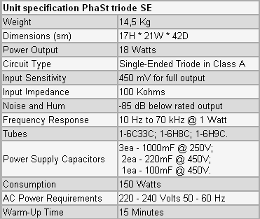
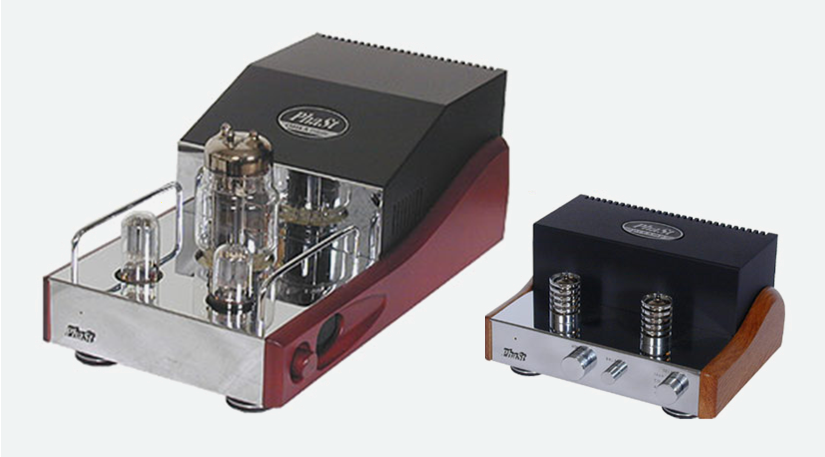
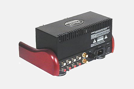
Eis o PhaSe 1 ( PhaSt)
- Amplificador ucraniano que uliliza a famosa válvula do MIG25.

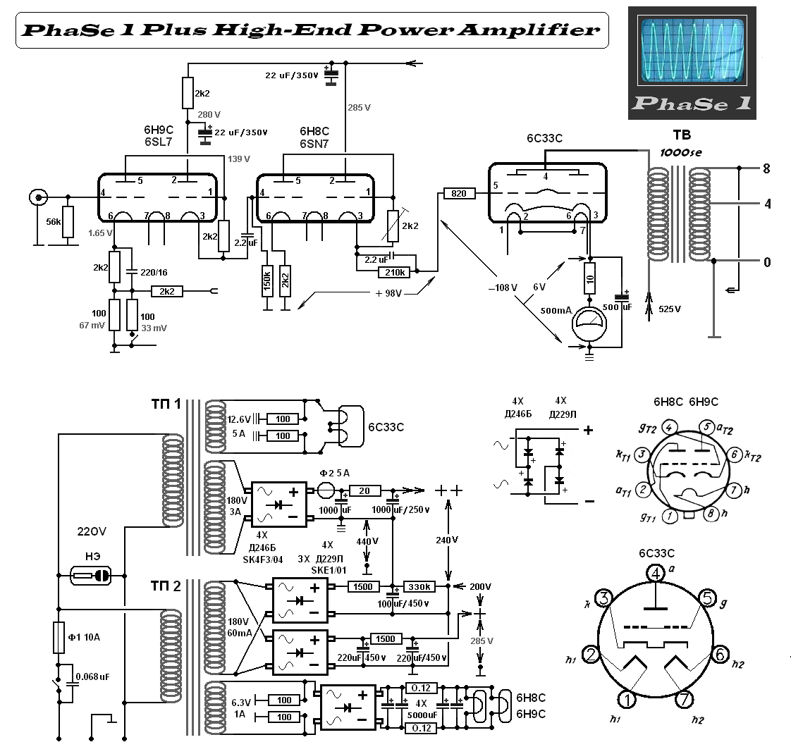
Amplificador mono canal. Unidade de potência.
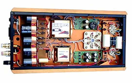
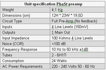
Amplificador e pré-amplificador.
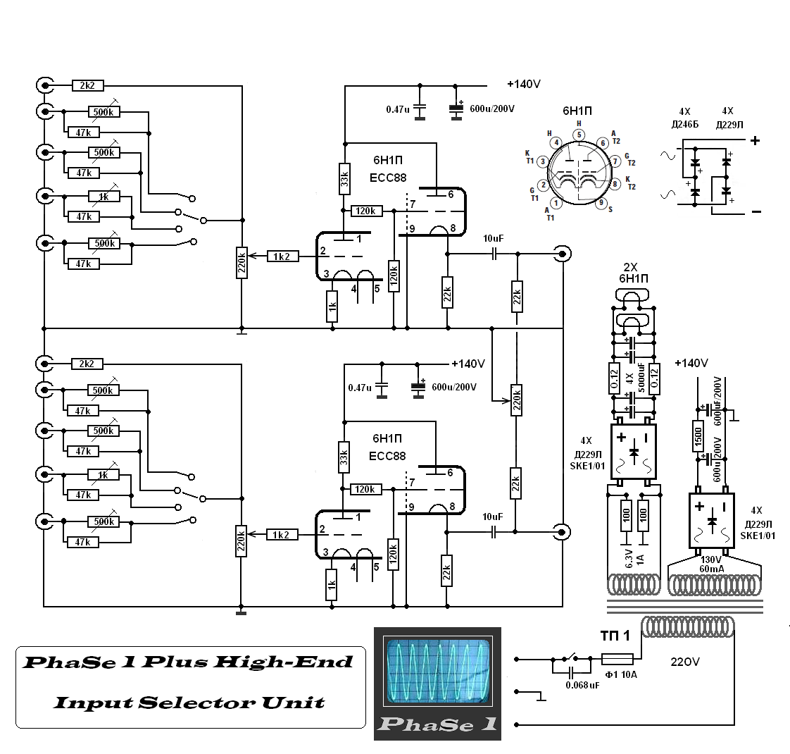
Pré-amplificador/seletor de entradas

Unidade para MC e MM.
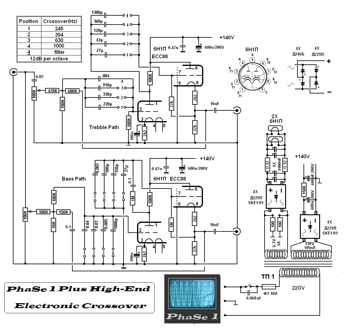
Divisor de freqüências para uso com dois amplificadores.
xxxxxxxxxxxxxxxxx
![]()
![]()