
Battery powered preamplifier
Adaptação do artigo original de Stefano Perugini
Publicado em Glass Audio nr. 2/98
Desenvolvido por Luiz Paracampo
Nos últimos tempos com o renascimento dos equipamentos de áudio valvulados, em que componentes de estado sólido não entram no circuito de sinal, vimos uma grande proliferação de aparelhos do gênero. Diga-se de passagem, o grande problema da válvula é sem duvida o filamento ou aquecedor. Este além de consumir certa quantidade energia, é também causador de zumbido quando alimentado com corrente alternada. A válvula em si tem duas enormes vantagens intrínsecas: Muito menos ruído de fundo que seus análogos de estado sólido, resistência ao uso pesado, diríamos abuso de trabalho indevido, em condições elétricas adversas, e o mais importante que é a linearidade de sinal e aceitar bem sobrecargas sem corte abrupto ou distorções gritantes nestas ocasiões. Assim porque não fazer uma unidade totalmente independente para funcionar em baterias? Isto já existia 60 e até mais anos atrás, afinal quando o radio iniciou, não havia redes elétricas disponíveis em todas as cidades e os rádios necessitavam de baterias para operar.
Voltando a esta antiga idéia com componentes atuais, resolvemos desenvolver um pré-amplificador de baixo ruído, isento de zumbido, com elevada estabilidade de operação, com alta confiabilidade, e totalmente isento de campos magnéticos espúrios.
Assim iniciamos nosso projeto de pré-amplificador universal para uso em estereofonia com cápsulas MC, MM, e para outros aparelhos auxiliares de novas gerações tais como I-pod I-cast e telefones celulares com conexão para rádio e TV. O sistema é simplíssimo e conjuga o melhor da tecnologia analógica e digital transformando os sinais aplicados em sinais analógicos de alta qualidade.
Enquanto o circuito de amplificação nos é bastante familiar à exceção das baixas tensões de operação, o circuito de fonte apear de simples é bastante sofisticado por anexar um carregador de baterias auto regulável com desligamento automático após a carga das baterias e um analisador do estado elétrico do conjunto de baterias.
Para alto desempenho do sistema escolhemos três baterias idênticas para uso em motonetas de 12V e 5AH, que se prestam muito bem ao bom funcionamento. O sistema tem decisivas vantagens teóricas de conceito e comprovadas vantagens operacionais sobre os outros tipos de circuito. O sistema é de alimentação direta; não possui osciladores ou sistemas de alteração das voltagens de fonte, enfim nada que induza do provoque ruídos estranhos. Infelizmente como nada neste mundo é de graça, Neste caso não há como aplicar a “lei do Gerson”. Anualmente V. terá que pagar por um novo conjunto de baterias.
O sistema da fonte não possui interruptores para recarregar as baterias, para que não haja nenhuma ligação com a rede. V. usará apenas o fio de conexão quando for recarregá-las, do mesmo modo que v. esta acostumado com seu celular.
Nota geral:
Em nosso circuito escolhemos válvulas de mais fácil obtenção e optamos pelo aumento da tensão de alimentação que favorece o funcionamento das mesmas, evita a saturação e minimiza a distorção geral. Dados gerais sobre o circuito original encontram-se na transcrição do artigo logo adiante. Em nossa sugestão adicionamos um pré amplificador para cápsula tipo Moving Magnet sem a adição do caríssimo transformador step –up. Pela análise geral do artigo poderemos verificar a relativa simplicidade do equipamento proposto.
Abaixo apresentamos o diagrama esquemático da fonte do pré-amplificador que fica montada no interior do próprio chassi do pré-amplificador.
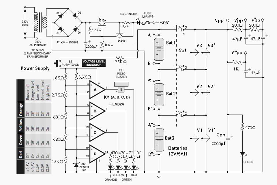
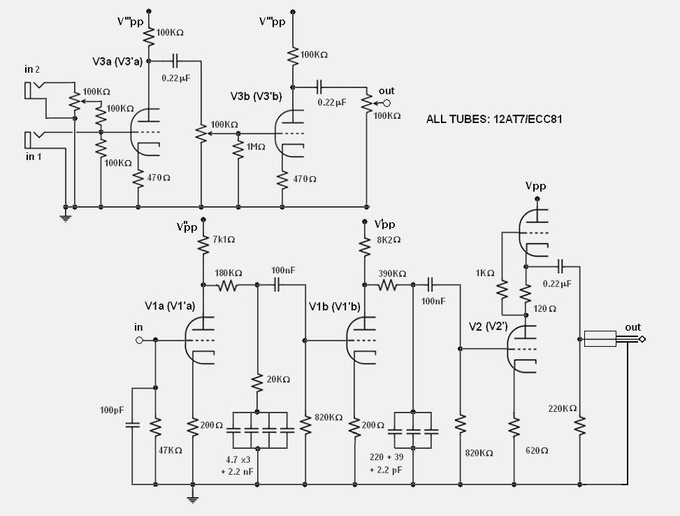
E aqui o diagrama esquemático das unidades de amplificação.
Ver também http://www.tnt-audio.com/clinica/preamble_n.html
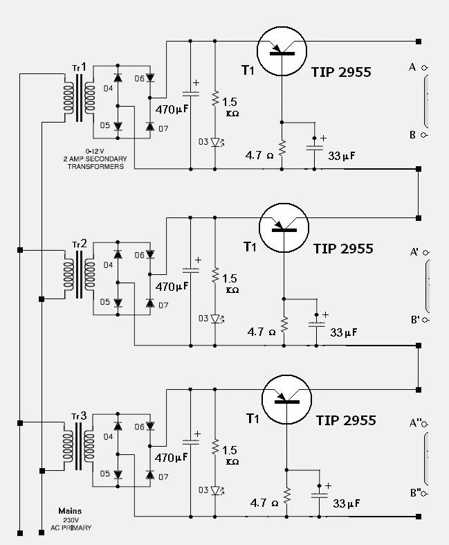
A fonte abaixo é um adaptador desenvolvido para a utilização do mesmo equipamento diretamente na rede AC sem uso de baterias.
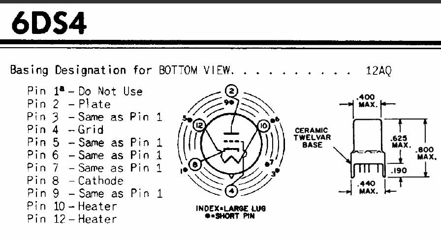
Preferred Substitutes .........................
6CW4
Nuvistor type used as grounded-cathode, neutralized rf amplifier in vhf tuners of color and black-and-white television and FM receivers. Requires nuvistor socket.
Bulb
.......................................... MT-4
Outline ....................................... 4-4
EIA Base ...................................... 12AQ
Heater Voltage
................................ 6.3 V
Heater Current ................................ 0.135 A
Triode
Input ......................................... 4.3 pf
Output ........................................ 1.8 pf
Grid to Plate ................................. 0.92 pf
Triode
Plate Voltage ................................. 135 V
Plate Dissipation ............................. 1.5 W
Class
A Amplifier
Plate Voltage ................................. 70 V
Grid No. 1 Voltage ............................ 0 V
Amplification Factor .......................... 68
Plate Resistance (approx) ..................... 5.44K Ω
Transconductance .............................. 12.5K µ![]()
Plate Current ................................. 8 mA
Class
A Amplifier
Plate Voltage ................................. 110 V
Grid No. 1 Voltage Derived from
Cathode Bias Resistor ....................... 130 Ω
Amplification Factor .......................... 63
Plate Resistance (approx) ..................... 7K Ω
Transconductance .............................. 9000 µ![]()
Plate Current ................................. 6.5 mA
xxxxxxxxxxxxxxxxxxxxxxxxx
Artigo original
The decline of the VALVES-ERA, that corresponds to the higher cheapness of solid state devices, was characterized by the achievement of vacuum tubes, able to comply the increased demands to manipulate the electric signal, with extraordinary features: Nuvistors, "computer grade" tubes, low-voltage tubes, high-tranconductance low-resistance tubes, etc.
With all respect for older and venerable valves, I believe that it is possible to obtain remarkable results, from a point of view of the sonic, by linking to the use of the above mentioned
typtology of valves the modern tools for the PC-based circuits analysis (like PSpice of the Microsim). All this make possible the "exploration" of areas seemingly forbidden to thermionic technology and also, to carry out objects that possess those sonic characteristics that have definitively decreed the revival of the electron tubes in the Audio World.
With this article I'll show how with the 12+12 volts produced by two batteries, a handful of components and 4 E188cc-SQ you can make a MM phono stage with remarkable sonic characteristics.
Start
In the world of the vacuum tubes it is inusual to meet with devices able to work at a low power supply. Among the signal triodes it is natural to think about the ECC86/6GM8; with its maximum plate voltage of only 30 volts, a transconductance and an internal resistance of 3.6 mA/V and 7K respectively, it represents the canonical choice when you want to elaborate the audio signal at low levels an low power supply. A series of experiments convinced me that, however, the use of valves, apparently not suitable for this aim, as the E88CC/6922 and E188CC/7308 (very similar tubes but not the same), can produce better results from the sonic point of view even at a low power supply. Between the two, I have fully preferred the E188CC/7308 because in this appliance I have found a better alectric response and a more pleasant sonic feature. But you must consider something else in addition: in the low plate voltages area you cannot refer to the typical electrical parameters carried on the data sheet; in fact both the transconductance gm and the m-factor besides the fact that they are inferior to the typical values (in average more than 50%), they present a stronger dependance on the plate and voltage current, as a consequence, you need a greater designing effort if you want to control the T.H.D. (total harmonic distortion) using "natural remedies". The way is really tortuous but once you achieve your aim, the low power supply, enabling you to an easy use of batteries, will repay you with a pureer sound, detailed and rich of microinformations.
From the virtual.......
When you design a phono preamplifier, the targets on wich focus your mind are two:
a) the control of the distortion in the overloading condition;
b) the synthesis of an accurate RIIA de-enphasis network.
To obtain the first result I've resort to the combined use of the local negative feedback
and the harmonic distortion cancellation technique. The latter, was often used at the dawning of the "vacuum age" but soon left, after Harold Black had his famous idea on the Lackawanna Ferry.
The harmonic distortion cancellation consists on the use of phase inversion characteristics, typical of a common-cathode gain-stage for example, in order to cancel, but actually only to reduce the harmonic distortion produced during the amplification process. You need, obviously, at least of two gain stage with complementary phase caracteristics.
To obtain the second result you must carefully model the single gain stages (so you must know exatly the gain factors, the input and output impedance) and tou must strategically set the three
main time constants that caracterize the RIIA de-enphasis network.
In Fig.1 you can see the block diagram of the preamplifier (ro1, ro2, ro3 are the output impedance; A1, A2, A3 are the gains of the single stages; ri1, ri2, ri3 are the input impedance), while in Fig. 2 you can see the all circuit. The first two time constants are synthetized by the network between the first and the second stage, the third constant by the network included between the second and the third stage.
The Split RIIA method [1], apart from the fact that it permits a more accurate de-enphasis characteristic, in making the phase response between the stages more homogeneous, it helps the technique of the harmonic distortion cancellation in its job.
In Fig.3 you can see the frequency response of the phono stage and in Fig.4 is the frequency response with inverse RIIA. The charts have been obtained with an evaluation version of PSpice while the model of vacuum tubes is that of Mr. Koren [2] in wich, however, to the EX parameter a law of the polynomial variation with the plate voltage has been ascribed in order to render more realistic the behaviour of the virtual tubes and then the whole preamplifier in the low voltage and low current area. The coefficients of of the polynome have been obtained using the least squares method on the experimental data.
The prject of this preamplifier requires a lot of care in the containement of the distortion in overloading conditions fixed at +22dB with respect to the nominal value of 5.0 mVpp @ 1kHz of the input voltage, that is 3.55 Vpp. The aim is that of not overcome the 1% value of T.H.D. in overloading conditions because, over this value, phenomena linked with the intermodulation distortion could be audible. The examination of the Fig. 5 shows that with the technique of the harmonic reduction only, you can't reduce the T.H.D. for a wide range of frequencies, therefore a small quantity of local feedback is peremptory.
The harmonic reduction has been optimized around the frequencies close to 1kHz, where the human ear is more sensible. The final results of hours spent simulating the preamplifier are reported in Fig. 6.
Even thoug the output impedance is quite low (see Fig. 7), I don't suggest to go under 50KW
as load, otherwise you'll have an unaccetable rise of the T.H.D.
........to the real
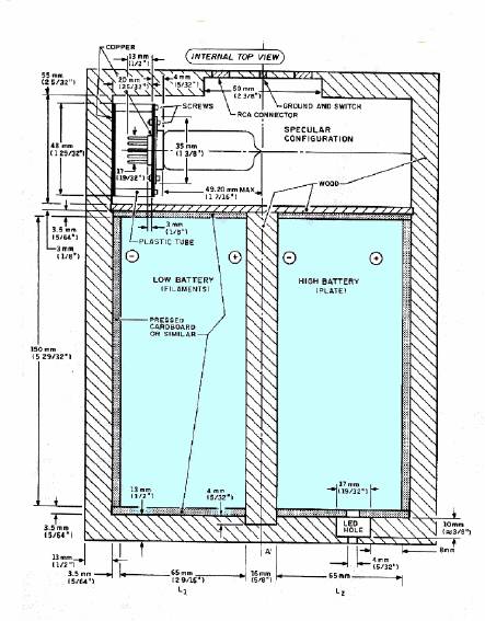
Fig. 8
The physical realization of the preamplifier is shown in Fig. 8. The results of measurements on the real preamplifier have been in perfect accordance with the results of the simulations. That must not be a surprise because the parameters of the mathematical model used have been obtained in an experimental way from the tubes used in the preamplifier and not grom the average characteristics reported on the data sheet. If you set your project using the PC-based circuits analysis, I suggest to spend a little more time on the correct validation of the mathematical model. In Fig. 9 you can see the simple power supply, very effective both on an economic and sonic point of view.
Universal Power Group
UB1250 batttery
YUASA equivalents
ECB1UD1030U, NP412, NP512, NPG5412, NPH512
A PSpiced low-voltage phono preamplifier with harmonic distortion cancellation.
|
Part list for phono preamplifier Resistors R1 7k1501W 1% E96 Series R2 47K5W R3, R8, R14, R15 200W R4 169KW E96 Series R5 20KW E96 Series R6 8K06W E96 Series R7, R12 820KW R9 390KW R10 1KW R11 120 W E96 Series R13 604W E96 Series R16 220KW All resistors are 1/2W, 1% metal film, unless otherwise noted Capacitors C1 100pF Silvered Mica ACL C2, C4 100nF 50V MKS 02 Wima C3 4.7 x3 + 2.2 nF ACL C5 220 + 39 + 2.2 pF ACL Silvered Mica C6, C7 47mF Electrolitic Rubycon 50V C8 0.22mF 50V MKS 02 Wima Vacuum Tubes V1, V2 E188CC-SQ Philips
|
|
Parts List for the Power Supply |
||
|
Bat1, Bat2 |
NP7-12, 12V-7Ah |
YUASA |
|
Rld |
1kW |
0.5W, 5% |
|
Dld |
LED, 3mm RED |
HP |
|
Cpp |
47mF, 63V |
Rubycon |
|
SW1 |
Bipolar Switch, 3A |
|
|
Parts List for the Battery Charger (All resistors are 1/4W, 5% carbon film, unless otherwise noted)
|
||
|
Resistors |
||
|
R1 |
3.3kW |
|
|
R2 |
1kW |
|
|
R3 |
180W |
|
|
R4,R5 |
1.1kW |
|
|
R6 |
1.5kW |
|
|
POT |
1kW |
Bourns |
|
Capacitors |
|
|
|
C1 |
470mF, 50V Electrolytic |
Rubycon |
|
C2, C4 |
100n, 50V MKS 02 |
WIMA |
|
C3 |
33mF, 25V Electrolytic |
Rubycon |
|
Solid State Devices |
|
|
|
D1,, D2, D4-D7 |
BY396P |
General Instruments |
|
D3 |
LED, 3mm GREEN |
HP |
|
IC1 |
L200 |
ST |
References:
[1] Morgan Jones, VALVES AMPLIFIERS, Newnes 1995, pp. 268-287;
[2] Norman Koren, "IMPROVED VT MODELS FOR SPICE SIMULATION", Glass Audio, 5/96, p.18;
[3] Charles Rydel, "SIMULATION OF ELECTRON TUBES WITH SPICE", AES preprint 3887 (G-2), 98th AES Convention, Paris 1995;
[4] Texas Instruments, ADVANCED BUS INTERFACE SPICE I/O MODELS, 1995 p. 1-10;
[5] F. Langford-Smith, RADIOTRON DESIGNER'S HANDBOOK, 4th Ed. 1953 pp. 535-537;
[6] SGS-Thomson, DATA on DISC CD-ROM.
|
APPENDIX
PSpice an the art of Harmonic Distortion Cancellation
The advantage of the PC-based circuit analysis is that to underline the more creative aspect of the design because it unable us to get free almost totally from the tediousness of the numeric and symbolic calculation that electronics drags everywhere. For example the right determination of the phase response in a complex circuit takes only few minutes, on the contrary, the same calculation done by hand and in a rough way could take much more time. Complex procedures of measurement that in the real world would require expensive instruments and long times of preparation, can be made in a short and economical way. In my project PSpice has been helpful to optimize the distortion characteristics of the phono preamplifier. I'll report below the followed procedure to obtain a result like that because I think that it can be used in other cases if properly adapted. a) "Initialize" the preamplifier (that's to say, find the best bias condition for the single amplification stage) and synthetize the RIIA de-enphasis network; b) With the PSpice statements .PARAM make variable the load resistance of the first gain stage and through the statements .FOUR and .STEP choose the value that produce the less T.H.D. on the output node; c) Repeat the same procedure, explained above, for the remaining common cathode stage or else (as in the SRPP case) operate reducing the superior cathodic resistance as to the inferior one on the respect of A1 Class.
|
xxxxxxxxxxxxxxxxxxxxxxxxxxxxxxxxxxxxxxxxxxxxxxxxx
![]()
![]()