
The “SKF-1” System
Among every proposition, carefully studied and experimented by the Moscow Science Academy, and evaluations took around by CFC Novacon, based on forums of ISU (International Stereoscopic Union) Netherlands, and from SCF (Stereo Club Français) France, We can dare say that our full proposed system is: THE BEST AND MOST AFFORDABLE PROCESS TO PERFORM THE REAL HIGH QUALITY 3D!
The complete set is composed of a beam splitter adapter to the objective and a set of coupling oculars intended to form the transparency viewer.
Distance between homothetic points (identical points in the two stereo images) taking pictures at 2m from the object
(mm) 17,0=0,5
Viewer amplifying (X) 3,5
Adapter dimensions (LxWxH) 52x120x62
Viewer dimensions (LxWxH) 120x135x65
Weight (uncased) (kg) 0,5
Included coupling rings M52x0,75
M49x0,75
The “SKF-1” was developed to render best results with “HELIOS-44” 58mm F.L. lens. With other objectives of 50mm F.L. results will be slightly lesser than optimum.
In all lenses
The splitter only allows diaphragms in the range f/2 to f/8
Remove the diffuser 1 (pic. 2) the slide picture sample, and the spring 3. In its place put the frame 3a
Elect the right coupling ring 4 and screw it into the objective filter thread.
On the formed unit, thread now up to the end, the ring 5 (pic. 1).
Put the splitter on the unit and go to the maximum position you can keep the splitter with its greater dimension in the same sense of the greater picture dimension of the camera. Now, tighten the set, unscrewing the ring 5 at the direction of the splitter.
The outfit is now ready to be used. You will see two images in the viewfinder. Focus and expose as usual.
If your camera has no exposure meter, or have an external one, put the ISO value the half stated on the film. This is due the system absorbs near 1.7 times the available light.
You will see in “How it Works”, that best results are obtained at f/4 .When needed diaphragm f/2 or f/2.8, it is absolutely necessary the use of the “limiter-sun-shade” nº 6 (pic. 1) . At f/ 5,6 or f/8 , never use part 6. More closed diaphragms, are unrecommended here, once they obstruct the ray paths in the objective when the splitter is used . So we recommend in daylight, in general, always slow speed films (no more than ISO 100) and high shutter speeds.
After some practices obtained from trial-and-error, you will feel the merits from “SKF-1” and the charming of high quality stereoscopic picture taking.
Mount the yellow ocular set 7 over the splitter. You have ready to see the stereoscopic slide viewer.
Each slide can be seen putting them inn the slot of the splitter. Individual focusing is obtained by turning to and fro the knob 5.
As all precision instruments, avoid mechanical bumps, thermal chokes and to force any element, also, avoid keep the instrument on humid and corrosive environments.
Under special request the “SKF-1” could also be adapted on several cameras 2 ¼ X 3 ¼ (6 X 9), 2 ¼ X 2 ¼ (6 X 6), 2 ¼ X 1 5/8 (4,5 X 6). (useful only rectangular format). Also in all digital cameras whose covering angle be near the 45°. (as shown in pic. 4)
>Transparency viewer “SDV-1” plastic body glass optical lenses.
>Stereo Goggles “RSV-1” adjustable interpupillary glass optical lenses.
>Table viewer “SSV-1” simple model.
>De Luxe foldable table viewer “SSV-2”.
>Attached portable projector. “STREGA-SDP”.
>Adapter “SKF-2” made for macrophotography from ½ ft up to 6 ft (0,15m up to 2m)
All complementary equipment can be seen at pics 6 to 12.
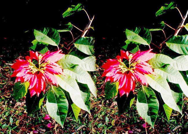
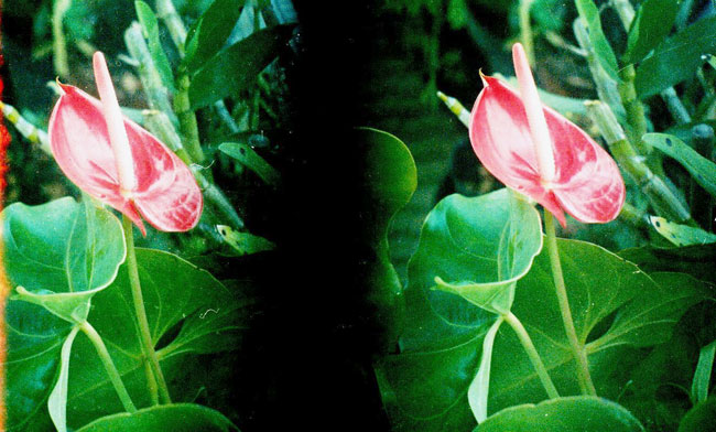
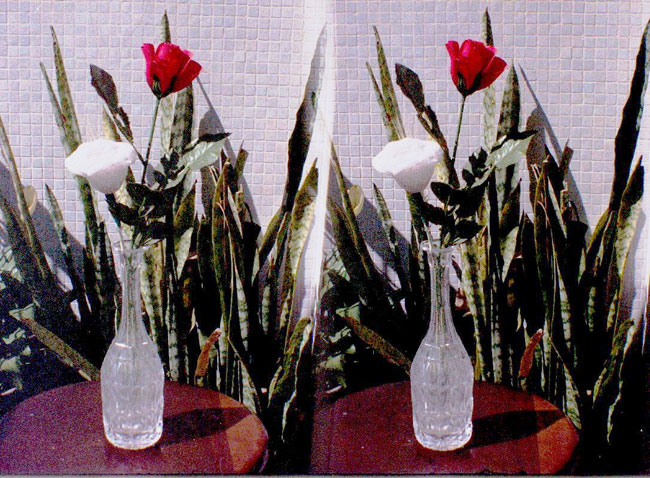
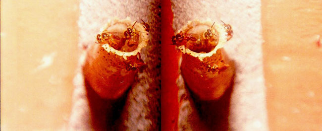
Pictures gentily yielded by the Dr. Abraham Spitz de S. Paulo city.
Technical Specifications:
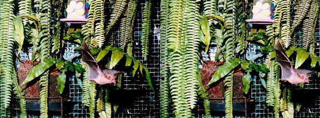
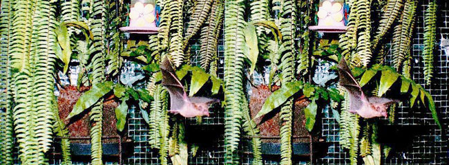
1 2 Flying bat Taken with infra-red sensor detecting the bat presence and firing the camera through electric relay. Electronic Flash picture.
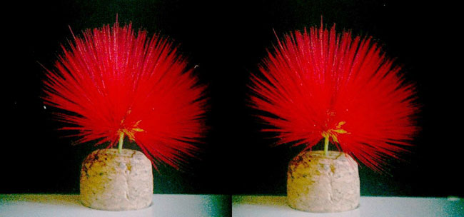
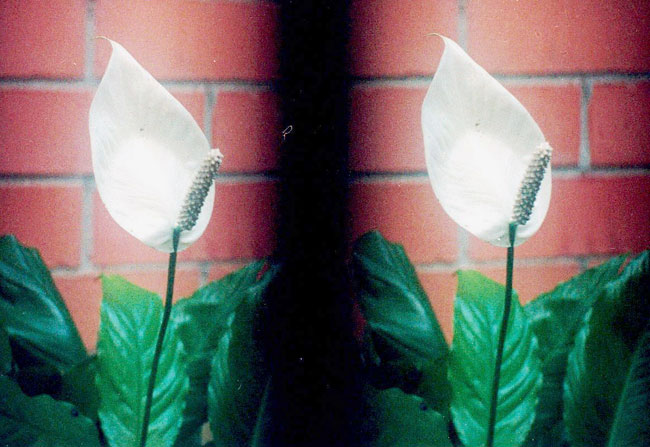
3 4 5 6 7 8 Using SKF - 1 with Nabla for close-up picture taking.
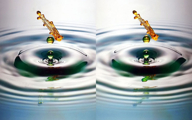
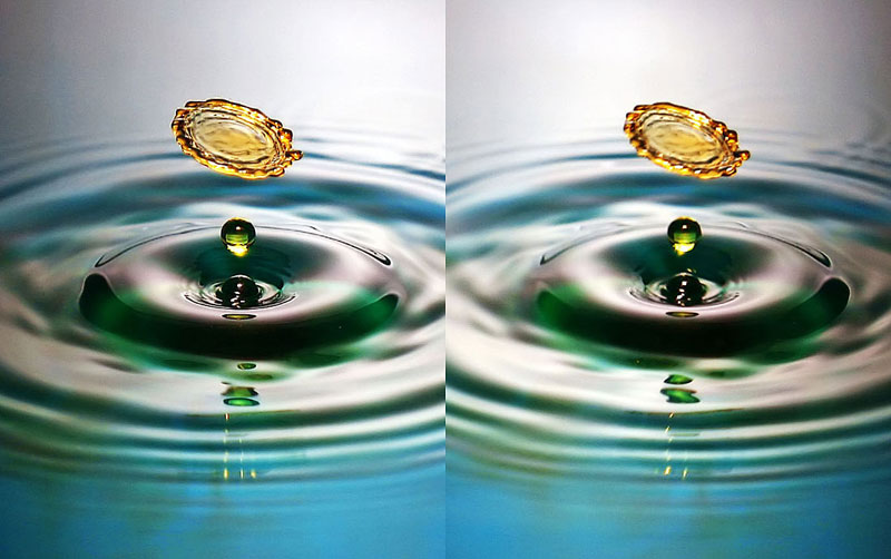
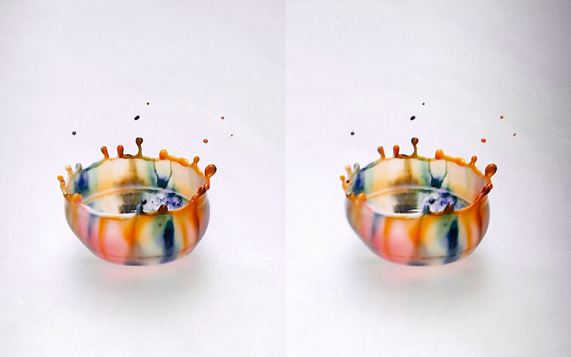
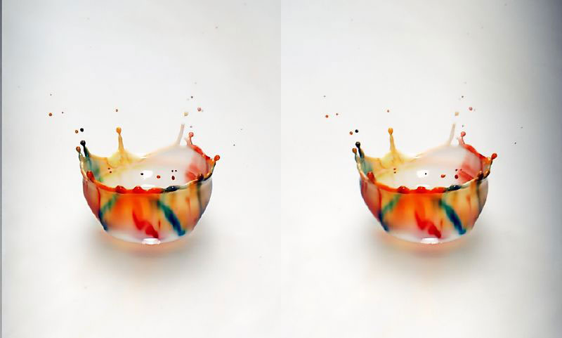
9 10 11 12 SKF -1 Nabla + Home built Strobo. Dr Spitz is an electronic engineer and developed a high speed Strobo with acoustic sensor that fires different colors at fast sequence of 1/2000 of second. With a controlled time lapse from the sound up to the light firing, he optimizes the bigger wave of better visual effect caused by the drop in the liquid. Each color remains only 1/6000 of second. The drops so shows
different colors as they change their forms creating varying colorful patterns caused by the variation of density of its surface.